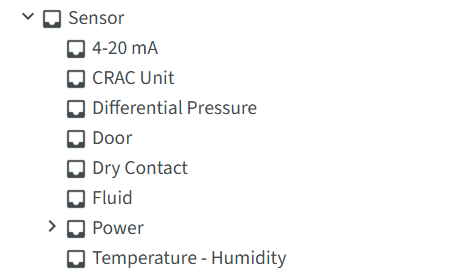
Sensor Types
Sensor Types are designed to work with RF Code Sensor Tags. They are primarily designed around the type of sensor data that a tag reports. In addition to the values directly reported from the physcial sensor, these CenterScape asset types can enhance the context of the sensor by classifying how it is physically installed and statistically enhancing the data through time series calulcations, group calculations, and providing context for higher location based group calculations.
Sensor Type Tree
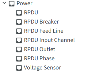
Sensor types include selectable types under the "Sensor" catagory. The Power catagory contains additional types related to power monitoring and the general "Power" catagory should not be used as a sensor type.
The power types are related to two types of RF Code Sensor hardware, the R171 Power Sensor and the R175/R170 RPDU sensor. Only RPDU and Voltage Sensor should be used to add new sensors in CenterScape as other RPDU types are dynamically allocated by the RPDU type.
4-20 mA
The 4-20mA sensor is deprecated and no longer available for purchase.
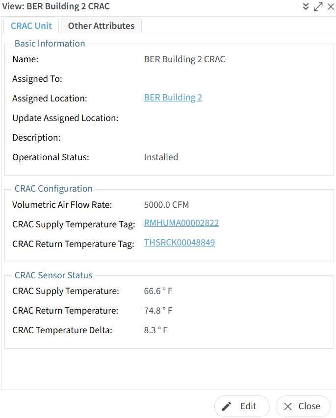
CRAC Unit
CRAC stands for Computer Room Air Conditioning. The CRAC Sensor type is a method to monitor the intake and exhaust temperature of a CRAC unit by measuring its supply and return temperatures. CRAC units typically ingest warmer air from above the raised floor of a datacenter and supply cold air underneath the raised floor.
The Return Sensor is mounted on the CRAC unit near or at the intake baffles and is usually an R156 sensor as the return air is v the raised floor. The supply sensor is typically a R151 Tethered Temperature Sensor with the broadcast unit mounted above the raised floor and the sensor probe mounted under the raised floor in the chilled air supplied by the CRAC unit. R156 sensors can also be used but mounting sensors under raised floor tiles or in ducting can cause poor quality radio signal reception.
Required Fields
-
Name - Name must be unique for any asset in the system. It is suggested that the term CRAC be included in the name for explanatory purposes.
-
CRAC Supply Temperature Tag - This tag id of the temperature sensor that measures the chilled air as it exits from the CRAC. It is recommended tha the sensor be mounted one meter or less from the cold air exit of the CRAC Unit for an accurate reading. If the Supply Temperature is located beneath a raised floor then use of a R151 tethered temperature sensor is recommended.
-
CRAC Return Temperature Tag - This is the tag id of the temperature sensor mounted near or at the point where ambient or hot air is ingested by the CRAC unit prior to chilling. If this air is ambient then a R156 sensor is recommended. If the air moves within duct work an R151 sensor can be used with the temperature probe located withing the duct work.
Recommended Fields
-
Assigned To - The summary location that the CRAC is located in. This is typically at room level but it can be at row or containment in some cases. If Assigned To is used then Assigned Loctation should be left blank as it will automatically be updated to the location of the Summary Asset.
-
Assigned Location - The node on the location tree that the CRAC unit is located at. Assigned Location is a direct entry to the location. If a Summary Asset is used for the location it is recommended that Assigned To be used. If both Assigned To and Assigned Location are supplied the Assigned To may override the Assigned Location after the asset data is saved.
-
Operational Status - The operational state of the sensor. This can be used to flag operational sensors in alerting and reports vs sensors that have not been deployed or for CRAC units in datacenters that are not yet ready for production.
-
Volumetric Air Flow Rate - This is maximum airflow that a CRAC is capable of. This is used for a Weighted CRAC Supply Temp and Weighted CRAC Return Temp by combining the Volumetric Air Flow Rate with the relevant temperatures. This takes into account CRAC units that have varying cooling capacities. If these metrics are not needed Volumetric Air Flow Rate can be left blank. Note: This is a general calculation that does not take into account variable speed fans in CRAC units since CRAC units do not have to be at their maximum capabilities.
Sensor Readings
-
CRAC Supply Temperature - The temperature of chilled air that the CRAC unit is supplying at the point of heat exchange. This is the live reading of the CRAC Supply Temperature Tag
-
CRAC Return Temperature - The temperature of air just prior to being chilled by the CRAC unit. This is the live reading of the CRAC Return Temperature Tag.
-
CRAC Temperature Delta - This is the live calculation of CRAC Return Temperature - CRAC Supply Temperature in relative Temperature units. This means that it is a Delta temperature reading. In the image above 8.3 Degrees indicates that the CRAC unit removed 8.3 degrees of heat from the air.
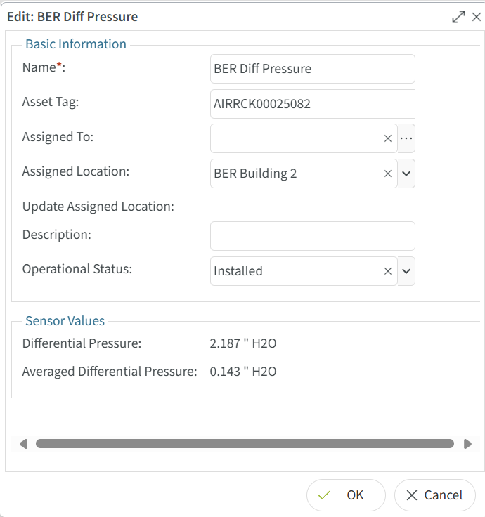
Differential Pressure
The R160 Differention Pressure sensor has two pressure sensors inside of it and measures the difference in pressure readings between the two sensors. The application for this sensor centers around heat exchange where cold air should be supplied to equipment and hot air should be removed from equipment after the equipment sheds its heat. Ideally the cold air will have a higher pressure than hot air so that hot air is not recirculated into the equipment. Should the hot air have a higher pressure than the cold air fans on the equipment will need to overcome the negative pressure and work harder for the same amount of heat exchange.
Required Fields
-
Name - Name must be unique for any asset in the system. It is suggested that the term AIR be included in the name for explanatory purposes.
-
Asset Tag - The id of the AIRRCK tag printed on the R160 case.
Recommended Fields
-
Assigned To - If using the pressure sensor in a room or possibly a rack with a summary asset the sensor can be assigned for the summary asset of the room or rack. If this is done the assigned location will automatically update to the location of the summary asset.
-
Assigned Location - Pressure sensors can be assigned directly to the location they are installed in. If this is done, Assigned To should not be used as it may override assigned location.
-
Operational Status - The operational state of the sensor. This can be used to flag operational sensors in alerting and reports vs sensors that have not been deployed or for pressure sensors in datacenters that are not yet ready for production and will not read as they would in a production environment.
Sensor Readings
-
Differential Pressure - These are the raw reading of differential pressure in Pascal for Metric users and inches of water column for Imperial users.
-
Averaged Differential Pressure - Since Differential pressure can change rapidly averaged differential is more commonly used as the point of monitoring. The average used is calculated based on an array of time series of Differential Pressure readings over a ten minute interval.
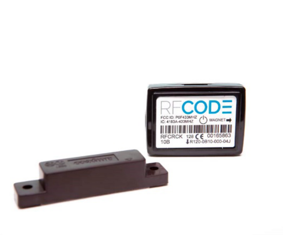
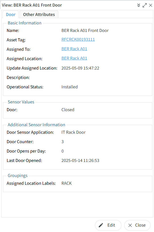
Door
The R120 Door sensor is designed to be installed on doors and sense whether they are open or closed. This could be any kind of door such as a IT Rack/Cabinet door, a Colo Cage door, a door to the datacenter, or the door of a mainframe computer. The door sensor records when a door is opened and when a door is closed not just when the sensor changes state. The door sensor continues to beacon the it is either open or closed every ten seconds reaffirming its current state every ten seconds. Door state changes happen immediately, meaning the sensor does not wait for the next 10 second beacon interval to send a new beacon but beacons within a few miliseconds when a door is opened or closed.
Required Fields
-
Name - Name must be unique for any asset in the system. It is suggested that the term DOOR be included in the name for explanatory reasons.
-
Asset Tag - The id of the RFCRCK tag printed on the R120 case.
Recommended Fields
-
Assigned To - Door sensors typically only use Assigned To if they are assigned to a Rack but can be assigned to DC Containment types as well.
-
Assigned Location - Door Sensors can be assigned directly to the location they are installed in and this is typically done for non Rack Locations where the sensor will not be moved. If this is done, Assigned To should not be used as it may override assigned location.
-
Description - Description should be used if the door is not a standard type to let users know more about the door the sensor is mounted to.
-
Operational Status - The operational state of the sensor. This can be used to flag operational sensors in alerting and reports vs sensors that have not been deployed or for door sensors in datacenters that are not yet ready for production.
-
Door Sensor Application - This classifies the type of door the door sensor is mounted to.
Containment Door A containment door is usually located at either end of the hot aisle. Containment doors restrict ambient air from entering into hot or cold aisles. In addition to access control knowing these doors have been open for a long time can help control the power and cooling the racks in the containment area. Classifying the door as a containment door allows for better context when creating alarms.
IT Closet The door to an IT Closet audits access to the assets inside the closet. If can also be flagged if it is opened for a long time if the closet has cooling. IT Rack Door These are doors on cabinets and are used exclusively for access monitoring.
Sensor Readings
-
Door - The Door attribute is mapped to the door sensor on the R120 Sensor Tag. "Open" indicates the door is open and "Close" indicates that the door is closed.
-
Door Counter - This is the total number of times the Door sensor has gone from closed to open in the current day.
-
Door Opens Per Day - This is the total number of times the Door sensor has gone from closed to open in the previous day.
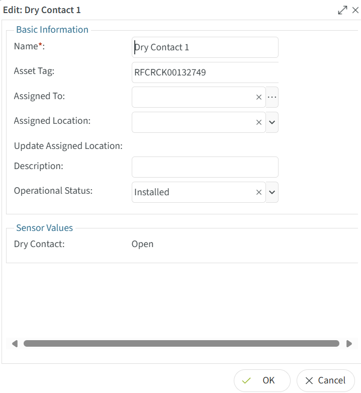
Dry Contact
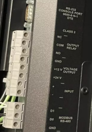
Dry contact senosrs are sensors that detect the open or closed continutiy in a circuit. Dry contacts can be normally open or normally closed. The R130 dry contact sensor is connected to dry contact ports of devices that support dry contact out put. The following image has a dry contact port that has a common loop that the black wire would be connected to and a "NO" or normally open port and "NC" or normally closed port that the red wire would be connected to. The information conveyed by the drycontact varries by devices and is sometimes configureable on the device to be monitored. Dry contacts are common in generators, CRAC units, UPS system, and security devices.
The basic configuration for a dry contact is to create an asset of the dry contact type. The schema is recommended to be customing by adding new types if many different types of dry contact applications are used. However if only a few dry contacts are used then the default dry contact type will work well.
Required Fields
-
Name - Name must be unique for any asset in the system. It is suggested that the name of the dry contact describes it purpose as well as a unique identifier. For example a dry contact sensor that senses that a rack mount UPS is on battery power could be "Dallas Rack A01 UPS Battery Monitor".
-
Asset Tag - The id of the RFCRCK tag printed on the R120 case.
Recommended Fields
-
Assigned To - Dry Contact sensors can be assigned to an asset but the types of assets they are assigned to are usually not in the default CenterScape Schema. With the exception of CRAC of which models can have dry contact output, equipment such as UPS, Generator, large PDUs, and electrical conditioning systems can be added as types to the CenterScape Schema and they dry contacts assigned to them. They will automatically get the Assigned Location of the parent asset if this is done.
-
Assigned Location - Dry Contact Sensors can be assigned directly to the location they are installed in and this is typically done for non Rack Locations where the sensor will not be moved. If this is done, Assigned To should not be used as it may override assigned location.
-
Description - Descriptions for Dry Contact sensors should include details on how the sensor is wired and what the sensor reading indicates.
Sensor Readings
- Dry Contact - "Open" indicates that there is no continuity on the dry contact Circuit. "Closed" indicates that the dry contact circuit is complete.
Fluid
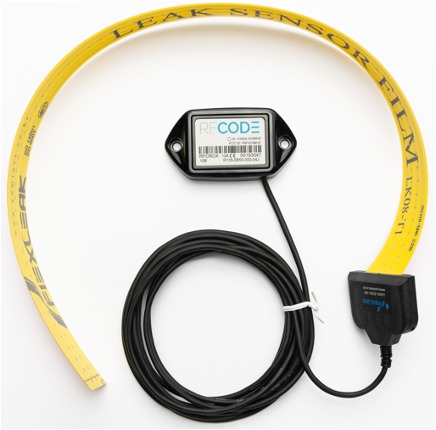
The Fluid type is used to monitor the condition of the R135 Fluid detection Sensor. The RFCode R135 is a film-based sensor that detects water or water-based fluids. It is used in various industrial applications, including detecting coolant leaks, condensation, and vulnerabilities to conductive liquids that threaten IT assets. The “wire-free” R135 Fluid Detector Sensor features a revolutionary thin-film leak sensor that can easily be applied to floors, walls, or even wrapped around pipes or other objects.
Required Fields
-
Name - Name must be unique for any asset in the system. For fluid sensors it is recommended that the world "Fluid" or "leak" be used in the name for descriptive purposes.
-
Asset Tag - The id of the RFCRCK tag printed on the R135 case.
Recommended Fields
-
Assigned To - This option is typically not used for Fluid sensors as they usually mounted to floors or equipment that is not easily moved.
-
Assigned Location - The room or area that a Fluid Sensor is mounted within.
-
Description - For fluid sensors a description of how the fluid sensor is mounted is recommended.
Sensor Readings
- Fluid Detected - "Dry" indicates that the fluid sensor does not detect fluid. "Wet" indicates that a fluid sensor detects fluid. R130 fluid sensor beacon every 10 seconds but will interrupt that cycle and beacon immediately on fluid state change.
Power
The power type is a catagory that includes sensors that monitor power. They are documented seperately from other sensor types.
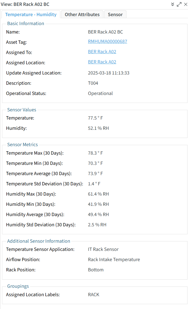
Temperature - Humidity
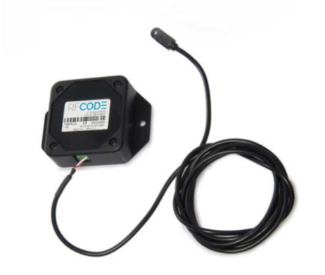
The Temperature - Humidity type is designed for R156 sensors. These sensors have measure both Temperature and Humidity readings and broadcast these readings every 20 seconds. They have a group code of RMHUMA. The R151 is a tethered temperature sensor with the RF, battery, and circuitry housed in a case and the temperature sensor mounted externally at the end of a cable. These tethered sensors have a groupcode of TMPRCK. Additionally older sensors such as R155 (group codes THSRCK, HUMRCK) and R150 (groupcode TMPRCK) are also supported by this asset type. Older sensors have different beacon rates.
Note: R150 and R151 sensors do not have humidity sensors so the humidity attribute will be null in those cases.
The Above Picture shows a R155 Temperature / Humidity Sensor
The Above Picture shows a R151 Temperature Sensor. The temperature probe is used where sensor readings are desired but an R155 cannot be used due to RF or accessibility constraints
Required Fields
-
Name - Name must be unique for any asset in the system. For temperature sensors it is recommended that the world "Temp" or "T" be used in the name for descriptive purposes. For rack mounted sensors a name like BER2.A01.Temp.C.R7 may be used to describe a sensor mounted on Rack A01 in Site BER2 on the Intake/Cold side of the rack on RU 7. A descriptive and unique name is especially important for Temperature sensors due to their high populations
-
Asset Tag - The id of the Temperature / Humidity tag printed on the tag case.
Recommended Fields
-
Assigned To - Assigned to preferred when assigning a sensor to a rack as the rack can be moved to a new location. When this happens the sensors will be moved as well. For other location types either Assigned To or Assigned Location can be used.
-
Assigned Location - The room or area that a Temperature Sensor is mounted within. If assigned to a rack using Assigned To this field will be automatically updated.
-
Description - A description for non-rack mounted temperature sensors is recommended. Rack mounted temperature sensors are typically very numerous and uniform to make a description cumbersome unless there is a special case.
-
Operational Status - This is very important for Temperature Sensors in order to make sure alarms are sent only when Temperature Sensors are ready for production use. The key is to use Operational Status = Operational as a method to bring a sensor under alert monitoring and not to send alerts for sensors that have yet to be deployed or that are in incomplete or empty data halls.
-
Temperature Sensor Application - Temperature sensors have two default applications in CenterScape. They can either be IT Rack Sensors or Room Sensors. IT Rack Sensor is used when sensors are mounted on or in front of or in the rear of Racks in such a way as they either measure the temperature of the air prior to being ingested or passing through equipment or after the air has been warmed by equipment. Room Sensor is used when temperature sensors are used to take a general temperature of a room.
IT Rack Sensor Options
- Airflow Position - This is the most important classification of an IT Rack Sensor. If the sensor is mounted on the intake side of the cabinet and it measures the colder air used to cool equipment then Airflow Position should be set to Rack Intake Temperature. For alerting and for other calculations, sensors that are classified as intake are handled differently. If the sensor is mounted in the rear of the cabinet or in such a way as it measures the temperature of the air after it has passed through the equipment in the cabinet then it must be classified as Rack Exhaust Temperature. In general, exhaust sensors typically have higher maximum temperature thresholds than intake sensors so alert thresholds that target intake or exhaust sensors use Airflow Position as a way to target the correct sensors.
- Rack Position - Rack position is used to determine the height of the sensor. Top, Middle and Bottom are used to describe where a sensor is located. If the exact U is desired the schema can be extended to support U level recording of the sensors, but top, middle and bottom is the default to support a wide variety of racks that large customers with multiple datacenters have acquired over years of operation.
Sensor Readings
- Temperature - This is the Temperature in Celsius or Fahrenheit depending on the locale reported by the browser. All temperatures are stored in Celsius and converted for presentation
- Humidity - The is the relative Humidity as measured by the sensor. Relative humidity indicates how close the air is to being saturated with moisture on a scale of 0 to 100%. Changes in temperature will change the volume of water vapor air can store and will also change the relative humidity.
- Dew Point - This is a calculation based on the current relative humidity and temperature. Dew point is the temperature at which the current level of humidity will cause condensation. The relative humidity is predicted be at 100% at this temperature unless water vapor is removed from the air with a dehumidifier.
- Temperature Max (30 Days) - This is the maximum temperature the sensor has recorded in the past 30 days prior to the current day. It is recalculated at midnight.
- Temperature Min (30 Days) - This is the minimum temperature the sensor has recorded in the past 30 days prior to the current day. It is recalculated at midnight.
- Temperature Average (30 Days) - This is the average temperature the sensor has recorded in the past 30 days. It is recalculated at midnight via a data window of 30 days.
- Temperature Std Deviation (30 Days) - The standard deviation for Temperature conveys how steady the temperature is for a given sensor over the past 30 days. The statistic is the average difference of collected values from the average. For example a standard deviation of 0.2 degrees means that the sensor is generally within 0.2 degrees of the average temperature. A deviation of 10 degrees means that the typical reading of the sensor is an average of 10 degrees from the average temperature. In datacenters this indicates large temperature cycles that may indicate a lag in CRAC contribution for specific points. Temperature Standard Deviation is measured in Delta Temperature not is absolute Temperature.
- Humidity Max (30 Days) - This is the maximum relative humidity the sensor has recorded in the past 30 days prior to the current day. It is recalculated at midnight.
- Humidity Min (30 Days) - - This is the minimum relative humidity the sensor has recorded in the past 30 days prior to the current day. It is recalculated at midnight.
- Humidity Average (30 Days) - This is the average relative humidity the sensor has recorded in the past 30 days. It is recalculated at midnight via a data window of 30 days.
- Humidity Std Deviation (30 Days) - The standard deviation for relative humidity conveys how steady the relative humidity is for a given sensor over the past 30 days. The statistic is the average difference of collected values from the average. For example a standard deviation of 2% means that the sensor is generally within 2% degrees of the average relative humidity. A deviation of %20 relative humidity means that the typical reading of the sensor is an average of %20 relative humidity from the average relative humidity. In datacenters this indicates either large temperature cycles, a failed dehumidifier, a nearby water leak, or the over introduction of high moisture air from outside that has not been dehumidified properly. Humidity Standard Deviation is measured in Delta Relative Humidity is not absolute relative humidity.